|
|
| ? |
|
? |
| ? |
Daylight Design
Daylight is a vital natural resource that will significantly improve the environment within any building. Rooflights provide three times more light than the same area of vertical glazing. They can also provide a much more even distribution of light, particularly in larger structures. Where vertical glazing exists, the effective area for natural lighting will only be within 6m of the wall containing the window. These facts are well understood by most people involved in building design. However the huge potential of rooflights to provide exactly the amount, type and distribution of natural light required to meet any given specification is not always appreciated. Rooflights can help to provide natural light with qualities appropriate to the use of the building.
Top of page
Energy Efficiency
On top of its many other benefits, natural light also offers passive solar gain i.e. a free heating source. Even in a rather dull climate such as the UK, passive solar gain provides significant potential to reduce energy usage. Buildings that enjoy high levels of natural light evenly spread throughout the structure, will be heated naturally for a considerable percentage of the year. If the structure includes thermal mass in the form of solid walls and floors, these will act as a heat store, collecting heat during the day and releasing it as the temperature drops in the evening, thereby reducing the need for artificial sources of heat throughout the entire day. If window and rooflight openings are maximised on the sunnier southern aspects of a building, and minimised on the cooler northern aspects, and this is combined with a well insulated, airtight structure containing reasonable thermal mass centrally located within the building, dramatic reductions in heating costs can be achieved. A reduction in the level of artificial light required in naturally lit buildings also helps to reduce energy usage. Designers should also take care to avoid solar overheating ? see Compliance section.
Top of page
Type of Light
Rooflights are not only the most effective way of allowing natural light into a building, they can also determine the type and amount of light entering the building.
Direct or Diffused
Direct Light ? As the name suggests light passes through the rooflight without any disruption or interference, entering the structure as a straight beam. It therefore gives strong light in a given area but less general light in the surrounding area. It is useful where strong light is required in an area for close detailed work such as painting, or in situations where a very natural environment is desired, or the designer wants people in the building to see the sky through the roof. Direct light will result in shadows and glare on sunnier days.
Polycarbonate, PVC and glass in clear and most tinted options provide direct light.
Diffused Light ? As the light passes through the rooflight it is scattered giving a much more even distribution of light into the structure below. It is useful when the requirement is for ambient lighting over a large area with minimal shadows. Most industrial, commercial and sporting facilities prefer diffused light for these qualities.
|
Direct Light
|
|
Diffused Light
|
|
|
|
|
|
|
|
|
|
|
|
|
|
Poor Distribution of Light
|
|
Good Distribution of Light
|
GRP in all forms, Polycarbonate, PVC, and Glass in patterned and opal tinted forms provide diffused light.
If a material providing direct light and one providing diffused light into the building have the same light transmission, they will let the same amount of light into the building, it is simply distributed differently.
Top of page
Amount of Light
Different materials and different tints of materials provide varying amounts of light into the building. In clear format most single skin rooflight materials will have a light transmission of 80%-90%. This must however be checked for the specific rooflight being used; material thickness, diffusing or colour tints, and number of skins can all affect overall light transmission.
In some situations the amount of light entering the building needs to be controlled, usually to prevent overheating. Tinted materials will limit the light entering the building. It is impossible to give a general guide to the light transmission achieved through the various tinted options available, as these vary not only from material to material but also from manufacturer to manufacturer.
Top of page
Rooflight Areas to Achieve Adequate Natural Lighting Levels
The Part L regulations state that wherever rooflight area is less than 20% the building designer must show there is adequate natural light, and also that rooflight area must always be a minimum of 10% for a space to be regarded as daylit (see Legal Requirements ? Thermal Performance in the Compliance section). However adequate is a vague term, and the regulations do not give any clear guidance on how much daylight or rooflight area is needed for different applications.
The building designer should select the light level most appropriate for the building use, and whether this should be measured horizontally or vertically; these are usually dictated by the use of the building.
It is important that designers also consider possible future change of use of a building when determining rooflight area, and ensure that daylight levels are sufficient for all likely future uses.
The CIBSE Guide A recommends that standard maintained illuminances are appropriate to the task(s) generally carried out in the building. A selection from CIBSE Guide A (Table 1.12) are listed below:
Table A: Examples of activities/interiors appropriate for each maintained illuminance
| ? |
? |
? |
? |
? |
|
Standard Maintained Illuminance (Lux)
|
? |
Characteristics of Activity/Interior
|
? |
Representative Activities/Interiors
|
| ? |
? |
? |
? |
? |
|
50 - 100
|
? |
Interiors used occasionally, with visual tasks confined to movement, limited perception of detail. |
? |
Corridors, Bulk Stores. |
| ? |
? |
? |
? |
? |
|
150 - 200
|
? |
Continuously occupied interiors, visual tasks not requiring perception or detail |
? |
Loading Bays, Plant Rooms |
| ? |
? |
? |
? |
? |
|
300 - 500
|
? |
Moderately difficult visual tasks, colour judgement may be required. |
? |
Packing, General Offices, Engine Assembly, Retail Shops |
| ? |
? |
? |
? |
? |
|
750 - 1000
|
? |
Difficult visual tasks, accurate colour judgement required. |
? |
Drawing offices, Chain Stores, General Inspection, Electronic Assembly, Supermarkets |
| ? |
? |
? |
? |
? |
|
1500 - 2000
|
? |
Extremely diffucult visual tasks. |
? |
Precision Assembly, Fabric Inspection |
| ? |
? |
? |
? |
? |
For manufacturing environments (and office spaces), the tasks being illuminated are usually in a horizontal plane, viewed from above, and it is usually more appropriate to measure light levels horizontally. For some applications (e.g. storage facilities and racking), the illumination of vertical surfaces may be more relevant, and light levels should then be analysed vertically. Note that inside any given building, the vertical illuminance levels are generally lower than horizontal - but lower light levels are often acceptable for tasks viewed vertically (such as storage facilities).
The possible shading effects of large obstructions inside the building should also be considered, as should rooflight layout to minimise this effect.
Independent research* submitted to the Building Regulation Advisory Council and being considered for inclusion in future revisions to the Building Regulations, has predicted the daylight levels in the horizontal and vertical planes inside typical large span buildings (assuming even rooflight layout, without any significant obstructions) using the latest computer modelling techniques.
*The independent research was carried out by the Institute of Energy and Sustainable Development, De Montfort University in 2003, and the results published as Daylighting and Solar Analysis for Rooflights.
This research does not define a definitive rooflight area for a particular application. Selection of exact rooflight area depends on the level of natural lighting desired, the percentage of a working year that lower natural light levels are acceptable, and the level of use of auxiliary lighting which is acceptable; these are more subjective, and should be determined by the building designer, although it is recognised that rooflight area should not be less than 10% in any daylit space, as specified in Part L2.
The research provides data on how often during a year rooflights of various area will provide any selected lighting level (and hence how often auxiliary lighting may be required). In general, if relatively small increases in rooflight area result in significant reduction in time that auxiliary lighting is required, they should be seriously considered; conversely, reductions in rooflight area can be justified where they do not result in significant increases in the time that auxiliary lighting is required.
Tables B and C taken from this research, provide recommendations for rooflight area to achieve desired lighting levels, on this basis, assuming overall light transmission of 67%; for rooflights with lower or higher light transmission, the figures should be adjusted accordingly.
Table B: Recommended Minimum Rooflight Area for Desired Illuminance Level (Horizontal)
| ? |
? |
? |
|
Illuminance Level Required in the
Horizontal Plane (Lux)
|
? |
Recommended Min Rooflight Area
(% of Floor Area)
|
| ? |
? |
? |
|
100
|
? |
10
|
|
|
? |
|
|
200
|
? |
10
|
|
|
? |
|
|
300
|
? |
13
|
|
|
? |
|
|
500
|
? |
15
|
|
|
? |
|
|
750
|
? |
17
|
|
|
? |
|
|
1000+
|
? |
20
|
| ? |
? |
? |
Table C: Recommended Minimum Rooflight Area for Desired Illuminance Level (Vertical)
| ? |
? |
? |
|
Illuminance Level Required in the
Vertical Plane (Lux)
|
? |
Recommended Min Rooflight Area
(% of Floor Area)
|
| ? |
? |
? |
|
100
|
? |
10
|
|
|
? |
|
|
200
|
? |
14
|
|
|
? |
|
|
300
|
? |
17
|
|
|
? |
|
|
500+
|
? |
20
|
|
|
? |
|
Top of page
Rooflight Configuration
The factors to consider when designing the rooflight configuration are:
- Is there sufficient general lighting to create a pleasant and suitable internal environment?
- Is there a requirement for increased or controlled light levels in specific areas of the building e.g. play area in a sports hall?
- The relationship between the height of the building and the diffusing quality of the rooflights to provide good general light at ground level.
- Degree of roof maintenance and roof access envisaged.
- Weatherability and minimising laps, especially between dissimilar materials.
There are a number of possible configurations for the rooflights.
Chequerboard Rooflights
This allows for individual rooflight units, both in plane and out of plane, and provides the most uniform distribution of light. The rooflight is fixed to the metal cladding or roof deck on all four sides and is therefore well supported.
This design has the maximum number of end laps or flashings and therefore requires the maximum attention to the sealing details by the roofing contactor with resultant increased costs. |
? |
|
| ? |
? |
? |
| ? |
? |
? |
Ridge Lights ? Barrel Vault Rooflights
Using a barrel vault rooflight along the ridge can provide an aesthetically pleasing design and a relatively uniform distribution of light only if the roof slope is short. The major advantage over the chequerboard arrangement is that they reduce the number of metal/translucent junctions to be fixed and sealed. However, at the ridge they are subject to high wind loads. Since it is recommended that rooflights should not be walked on at any time, where roof access is expected and frequent, ridge lighting provides a safer option. |
? |
|
| ? |
? |
? |
| ? |
? |
? |
Ridge to Eaves ? In Plane or Barrel Rooflights
Both profiled and barrel rooflights can be fixed from ridge to eaves or from ridge downslope. They minimise the number of metal/translucent junctions and could eliminate rooflight end laps, thereby improving reliability and servicing. However, since the rooflight industry does not recommend walking on rooflights at any time, a ridge to eaves layout will limit access across the roof. |
? |
|
| ? |
? |
? |
| ? |
? |
? |
Mid Slope Rooflights
This configuration is only possible with rooflights which match the roof profile. It provides a compromise between chequerboard and ridge to eaves in terms of light distribution and buildability. It avoids all areas with high wind uplift and allows general roof access if the metal roof is suitable for walking on. This design is now very popular on new build work. |
? |
|
| ? |
? |
? |
| ? |
? |
? |
Continuous Run ? In Plane Rooflights
Good levels of lighting achieved but less used on modern design. Care needs to be given to manufacturing and fitting tolerances of the metal sheets and rooflights to avoid a build up of tolerance difference.
Replacing old reinforced glass fixed in T bars with modern profiled rooflights or panel systems is common practice and very effective. |
? |
|
| ? |
? |
? |
| ? |
? |
? |
North Lights ? In Plane Rooflights
This configuration could be viewed as a continuous run as above but is not subject to tolerance difference between metal sheets and rooflights. North lights on new build is no longer common practice but refurbishment with modern rooflights or panel systems is easily achieved. |
? |
|
| ? |
? |
? |
| ? |
? |
? |
Random Design on Flat Roofs ? Barrel and Dome Rooflights
Used on flat or low pitch roofs, the rooflights are placed according to need and roof design on purpose designed upstands. |
? |
|
| ? |
? |
? |
| ? |
? |
? |
Curved Roof ? Barrel Vault Rooflights
Placed on an upstand that curves to the roof, barrel vault rooflights can be applied to run over the crown of the roof and stopping either mid slope or down to the eaves. Ideal for metal standing seam system roofs and single ply membranes. |
? |
|
| ? |
? |
? |
| ? |
? |
? |
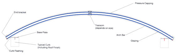
Structural Glazing
Bespoke structures of almost any shape and design, normally constructed from aluminium or steel sections and glazed with polycarbonate or glass units of varying specifications. These custom built structures are generally detailed by the rooflight manufacturer to an architects brief and allow immense freedom of design. |
? |
|
Top of page
Assembly and Accessories ? In Plane Rooflights
Fixings
The mechanical properties of plastic rooflights differ from metal and fibre cement sheets. They are more flexible and can have a lower fastener pull through value (i.e. Suction loadings which pull the rooflights over their fasteners).
The pull through performance values of fastener assemblies should be determined in accordance with Annex B: BS5427: Part 1: 1996.
Fasteners are required to be watertight and to restrain the rooflights without damage when subjected to wind loads determined in accordance with BS6399: Part 2: 1997 ? Code of Practice for Wind Loads, and support the design snow loadings described in BS6399: Part 3: 1988 ? Code of Practice for Imposed Roof Loads.
When required, rooflight manufacturers can provide guidance for calculating wind and snow loads covered by the above Code of Practices. Load calculations outside the scope of the above documents should be provided by a structural designer.
Assembled rooflights are also required to meet the HSE non-fragility requirements as detailed in Section 5. The number of fixings, the size of washer, purlin centres and location of fixings will have a bearing on the non-fragile performance of the rooflights.
Fig.1 ? Site Assembled Double Skin ? Cross Section
To meet the above design loadings and the non-fragility requirements, washers of at least 29mm diameter should be used in conjunction with 5.5mm diameter primary fasteners. The preferred location of the fasteners is usually in the bottom flat troughs of profiles (see below), except for continuous sinusoidal profiles which have no flat area where crown fixings should be employed.
To prevent build up of rainwater behind the fasteners, the washer diameters should be at least 10mm less than the trough width. Wide troughs may require more than one fixing in each trough.
When sheets are fixed through the crown of the corrugation, rigid profile shaped supports are required between rooflights and supporting members to enable the fasteners to be correctly tightened without distorting the profile.
Roof purlins must have a level face parallel to the roof plane, otherwise if twisted the rooflight liners will deform.
NB: With the new Thermal Performance Regulations, the additional weight of insulation and accessories may be an issue regarding roof purlin design.
Fig.2 ? Site Assembled Double Skin ? Longitudinal Section
Where buildings are in non-exposed locations, less than 10 metres high, and have limited permeability, wind loading is usually less than 1.2kN/m2 in general roof areas. GRP rooflights in 32mm deep trapizoidal profiles of weight 1.83kg/m2 and 2.44kg/m2 can be used at purlin centres of 1.8 metres and 2.0 metres. Similarly profiled polycarbonate rooflights of thickness 1.2mm can be used at purlin centres of 1.5 metres. In all cases the rooflight should be fixed at all purlins with 29mm diameter washers on fasteners, and a minimum of five fasteners across the sheet width.
Heavier or thicker rooflights, or reduced purlin centres will be required when rooflights are located in areas of high local suction wind loading adjacent to roof verges and ridge.
Provided that rooflights, located in the general roof area, are installed to meet the design wind and impact loadings, they will support the snowloads likely to occur in the UK. When rooflights are used in zones where:
- exceptional high loadings may occur
- on high buildings
- adjacent to abutments
- where valleys abut parapet walls
- other obstructions where snow drifts are likely; then heavier weight rooflights will probably be needed.
Plastic rooflights are more flexible than metal and fibre cement sheets. Whilst this allows these sheets to deflect to a greater extent without damage the following criteria should be adhered to:
- Limit wind load deflection to 1/15th span or up to 100mm total deflection, to prevent excessive wear around the fasteners.
- Snow loadings should not deflect the rooflights to more than 1/15th span or never more than 50mm, to avoid disruption of sealants which may cause end laps to birdmouth.
On built up site assembled rooflights, it is recommended that the liners and the top sheet assembly is fitted progressively across the roof. If lining out only, contractors must be fully aware of CDM non-fragility requirements for both rooflights and opaque sheets. To prevent any distortion of liners, always fix progressively from one end. Do not secure each end prior to fixing at intermediate purlins.
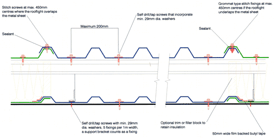
Stitch side laps at centres not exceeding 450mm. On exposed sites and roof pitches below 100, reduce centres to 300mm. Stitch rooflight to rooflight with roofing bolts or proprietary fasteners, which provide adequate support on the undersides. Where rooflights overlap metal sheets, self tap screw fasteners may be used.
When drilling for side lap fasteners, where the rooflight underlaps care must be taken not to push down the underlap with the drill. When the drill bursts through the outer sheet, the drill should be lifted to allow the liner to recover and then continue drilling with care.
Primary fasteners should not be fixed within 50mm of the end of the rooflight, after allowing for on site tolerances, unless provision is made to reinforce the edge of the rooflight, (a typical example is the built up/end upstand on factory assembled units).
Where rooflights extend to the bottom of the downslope (e.g. at eaves or valley) the overhang should not exceed 150mm.
Due to high thermal expansion coefficient of PVC and polycarbonate rooflights, over sized holes are required around the primary fasteners to accommodate the thermal movement without stress. On such rooflights up to 3 metres long over size holes should be 10mm diameter. On sheets up to 4 metres long over size holes should be 12mm. Due to high thermal movement, the length of PVC and polycarbonate rooflights should not exceed 6 meters and at this length a very high standard of workmanship at installation is required.
GRP rooflights do not normally require any special provision to allow for the thermal movement.
Application
To comply with the statutory requirements discussed in the Compliance section, rooflights used on insulated and heated buildings should be double or triple skin construction. They may be assembled on site as a built up system or fabricated as a single component under factory conditions.
Use site assembled rooflights with in situ insulated double skin roofing systems. Factory assembled rooflights are used in conjunction with composite panels or under purlin lining systems.
Rooflights assembled on site, consist of top sheets and liners to match the profiles of the adjacent opaque roofing systems. On low U-value rooflight systems, proprietary profiled sheets or other insulating layers are installed between the top sheets and the liners.
On factory manufactured insulating units, flat or profiled liners with upstands to form a box are bonded to the underside of the external sheet. Also, low U-value assemblies incorporating additional insulating components between the sheet skins are available.
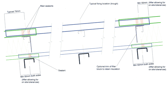
Sealants
Seal end laps on external weather sheets with two runs of preformed sealants applied within 15mm on each side of the primary fasteners. Ensure that sealants are well bedded into the corrugations prior to the application of the overlapping sheets.
When rooflights overlap rooflights or overlap metal, an additional seal close to the end of the lap will restrict dirt and moisture ingress.
Seal weather sheet side laps with at least one strip of preformed sealant tape located out board of the side lap stitchers (sealant laid in line with side lap fasteners can twist and become distorted when drilled through).
On built up assemblies, translucent liners form an integral part of the vapour sealed lining system. It is recommended that each side of the translucent liners should overlap the metal liners, and be sealed with 50mm wide film backed butyl tape applied over the joints between the translucent and metal liners. Seal end laps with a similar tape or a single run of sealant fixed above the fasteners.
Where the vertical upstands of factory assembled rooflights abut composite panels, they may be effectively sealed with closed cell, foam plastic strip.
Although adequate sealing will control moist air entering the rooflight in new build, some temporary misting may occur on the underside of the external sheet, particularly on cold, clear, frosty nights. This is normal and the misting will disappear as the structure dries out.
Polycarbonate rooflights should not come into contact with plasticisers, and barrier tape (not PVC) should be used to prevent contact with plastisol coatings on steel sheets.
Top of page
Assembly and Accessories ? Out of Plane Individual and Continuous Rooflights
Fixing Requirements and Weather Tightness
Fixing requirements vary slightly between rooflight manufacturers but the general curb/dome arrangement remains the same. However, the curb installer must follow the instructions supplied with each particular type of rooflight.
When using a preformed metal, plastic or GRP curb ? Figure 3, this must be fixed squarely to the roof structure which surrounds the rooflight opening using appropriate fixings e.g. wood screws in the case of a timber structure.
Fig. 3
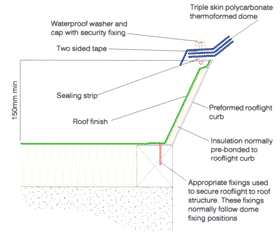
An allowance will need to be made within the roof construction for the height of the roof insulation, in order that a 150mm clearance can be achieved from the top of the finished roof weatherings to the top of the rooflight curb. It is important to continue the roof weatherings to the top of the preformed curb, thus providing a continuous weathertight seal. Where vents are incorporated into the side of the curb, the clearance must be at least 150mm to the underside of the vents before a break in the weatherings.
If no allowance is being made within the roof construction for the thickness of the roof insulation, an extra high preformed curb should be specified as necessary in order to maintain the 150mm minimum installation of the dome above the roof surface.
When domes are supplied complete with preformed curbs, the fixing holes in the domes are normally pre-drilled. Should it be necessary to drill fixing holes, these must be oversized to allow for thermal movement.
Care should be taken when bonding torch applied membranes and flashings to a preformed curb, and this should be completed prior to the installation of the dome. Many single ply membranes can be cold bonded to the preformed upstand, therefore, is possible to apply these following installation of the dome.
Prior to fitting the dome, it is important to fit a sealing strip around the entire perimeter of the fixing flange and fixing washers must be compressed onto dome, again maintaining a weather tight seal.
Many intermediate sections are available for fitting between the preformed curb and dome, such as ventilators, access hatches and smoke vents. These are normally factory fitted to the preformed curb, however, should site assembly be necessary, the installer must follow the particular manufacturers instructions.
Where a dome is to be installed directly to a builders timber curb ? Figure 4, an allowance must be made within the roof construction in order that a 150mm clearance is maintained between roof weatherings and the top of the finished curb. It is advisable to continue the flashings over the top edge of the curb.
Fig. 4
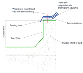
Many intermediate adaptor sections, vents, etc., are available for installation between the builders timber curb and dome, and these should be fixed in accordance with the manufacturers instructions.
The sealing strip, which must be continuous, is applied to the top of the builders curb prior to the installation of the dome, which will normally allow for overlap of the flashings assuming the curb is level and fixed squarely.
Barrel vault rooflights are available in all rooflight materials to suit standing seam systems, secret fix systems, flat and curved roofs. There are numerous designs which employ different methods of construction although all types are normally fixed to a curb support structure or similar.
The manufacturers fixing and sealing recommendations must be followed to ensure that weather tightness, impact resistance, durability and insulation requirements are maintained.
Fig.5 illustrates a typical cross section of a barrel vault rooflight. These are available in a range of widths to match the system that the rooflights are used with. Barrel vault rooflights can provide varying lengths and widths as required.
Fig.5 Barrel Vault Rooflight ? Cross Section
Top of page
Durability
Durability is the ability of a building and its parts to perform its required function over a period of time (BS7543). Virtually all materials will change physically when subject to UV radiation, moisture and atmospheric pollution. This change may well affect both their performance and appearance. The designer must therefore ensure that, not only will the materials and details used be suitable initially, but also that they will have a satisfactory life if the necessary maintenance requirements are met.
Materials
When considering in plane rooflights, the materials selected for both the roof cladding and rooflight can have a significant effect on the durability of the rooflights, and the amount of maintenance that will be necessary during their life. Components which are exposed to the weather and sunlight are particularly important.
The type of rooflight materials and roof sheeting colour must both be considered. Generally light coloured roof sheets are preferable because they do not absorb as much sunlight as dark colours, and they are therefore cooler. This means they will have less effect on the rooflight laps, which tend to deteriorate more quickly at higher temperatures. Similarly light coloured seals and fillers should always be used. This is particularly important with thermoplastic rooflights, and generally it is not an issue for GRP thermosets. Lighter roof sheet colours also have the best life and they optimise the thermal performance of the roof. The performance might also depend on the shape and orientation of the building and the environment.
Out of plane rooflights are generally not affected by the surrounding and adjacent materials, being isolated from them by the upstands, curbs and isolating systems. They are however, similarly subject to the same rules regarding fillers, seals and other components. Normally however, the rooflight will be delivered in a condition such that it can be incorporated directly into the roof assembly.
All rooflights are subject to gradual deterioration which will cause fading, discolouration and embrittlement, with some PVC being particularly susceptible. Plastic rooflights are generally resistant to normal pollution inthe atmosphere, provided the products have been protected with UV light inhibitors, and suitable surface protection.
With the use of special coatings and films the products can be used in aggressive chemical environments. Resistance to discoloration, surface degradation and embrittlement depends, to a large extent, on the surface protective treatment used by the manufacturer.
GRP
Most GRP rooflights will remain structurally sound for 30 years or longer. UV light and weathering could cause discolouration and surface erosion (thinning), but does not cause embrittlement or weakening of the sheets. Long term performance depends on environment, quality of sheets and surface protection, and maintenance. Discolouration of unprotected sheets can begin within 5 years, but good quality sheets incorporating UV absorbing surface protection (as supplied by all NARM members) will usually prevent significant discolouration for at least 20 years with the right maintenance program, and can virtually eliminate UV discolouration throughout their life. Higher fire resistant sheeting discolours more quickly when exposed to UV light due to the effect of the fire retardant additives.
Polycarbonate
The current generation of polycarbonate rooflighting products are manufactured from high quality extruded sheet material. With these materials, not only is there a high level of basic UV inhibitor but also co-extruded protective layer on both faces of the sheet. This is known as enhanced UV protection and always carries a manufacturers warranty. Additionally, the sheet manufacturer often warrants the performance of the material, even after thermo-forming.
Polycarbonate rooflights can be expected to be fit for the purpose, in excess of 15 years, with a slow (but documented) deterioration of light transmission and strength. Some enhanced UV protected high performance polycarbonate products have a life of 15 ? 20 years. As with many high performance materials, care must be exercised with regard to compatibility with adjacent materials. Some roofing sheet finishes (for example plastisol coated steel) can, over time, affect the mechanical performance of the product and an appropriate isolating system should be applied.
PVC
Most PVC darkens and embrittles under UV radiation providing a useful life of 5-10 years. Specially formulated and protected grades are available and, if properly fixed, can last over 20 years. PVC, especially in cold conditions, should always be treated as a fragile material and should therefore not be used on industrial/commercial buildings, unless additional means are provided in the design to prevent falls through the rooflight.
Fasteners
In Plane Rooflights
Both plated carbon steel and stainless steel fasteners are available. In most situations involving coated steel cladding and rooflights, plated steel fasteners provide acceptable performance as long as their heads are protected from the elements. Integral plastic heads are more reliable than push on caps, and the use of poppy red heads for rooflight fasteners is recommended. Stainless steel fasteners can be used for improved durability, and must be used when fixing to aluminium sheets to prevent bi-metallic corrosion.
The durability of the fixings will affect the non-fragile status of the rooflights, and care must be taken to ensure the fixings? durability is compatible with the specified or stated non-fragile life of the roof and rooflights.
Modular and Vaulted Rooflights
Always use stainless steel fixings, grade A2 to BS6105, with the fixing type being chosen to suit the supporting substrates.
Design Details for In Plane Rooflights
Rooflights must be assembled correctly in order to achieve the maximum durability. Avoiding water and dirt traps, by ensuring satisfactory slopes and end laps, is particularly important with in plane systems.
The frequency of fixings and the size of the washers, needed for rooflights and rooflight liners, will generally be different to that of the surrounding metal sheets.
Rooflights will also require side lap stitching. A full fixing specification must be obtained from the rooflight manufacturer to ensure long term durability and non-fragility.
Design Details for Out of Plane Rooflights
Generally these rooflights are delivered in a format such that they can be incorporated directly into the roof construction. If site assembly is required, the component parts are prefabricated from suitable materials.
Maintenance
The durability of any rooflight, regardless of the material from which it is made, is always dependent on regular maintenance. Maintenance regimes vary from manufacturer to manufacturer, and each should be approached for their specific recommendations according to their warranty, but in general terms, the requirements can be described as follows:
Cleaning
Clean regularly to maintain the highest levels of light transmission, usually every 12 months. As well as affecting light transmission, surface contamination can affect the heat absorption of many glazing materials, and this in turn can affect the long term physical and optical properties.
The cleaning process is generally uncomplicated, consisting of washing down with warm water and mild detergent. Abrasive, caustic and chemical treatments are unnecessary, and may actually cause damage to the exposed surfaces of the rooflight. A soft cloth or brush may be used to remove persistent contamination. In the case of paint or bitumen splashes, white spirit or alcohol applied with a soft cloth may be used with care. A final rinse with clean water will complete the process. Pressure hoses should not be used as the high pressure water can penetrate the sealing systems.
Inspection
Rooflights should be inspected at least once a year. This is often best combined with a cleaning process. The surface of the rooflights should be checked for damage, and any found should be repaired in accordance with the manufacturers? instructions. Any damage which penetrates the surface protection of the units will, in time, affect the ability of the unit to resist impact, and with the advent of non-fragile systems, this is particularly important.
Finally, all fixings should be checked for tightness and corrosion. Many non-fragile systems rely on the security of the fixings to achieve their impact performance potential. Any fixing found to be inadequate should be replaced.
Every second or third inspection should include a check of the sealing systems, replacing any that are showing signs of failure.
Note:
Obviously, the frequency of inspection and maintenance must be tailored to suit the local environment conditions on the roof in question, with higher levels of aggressive atmospheres requiring shorter inspection periods.
General
Although rooflight degradation can be minimised by careful specification, attention to detail during construction, inspection/repair and frequent cleaning, the rooflights are only likely to provide adequate daylighting for 20 to 25 years. Replacement must be anticipated during the life of the building. More detailed information can be obtained from individual manufacturers. ?
Long Term Non-Fragility
Provided rooflight products are fixed in accordance with the manufacturers recommendations, rooflights manufactured by NARM members will be designed and produced to be non-fragile when installed, unless stated to the contrary. As with most other roof cladding materials, it must not be assumed that the non-fragility status will last the life of the building.
Good quality GRP rooflights have a service life in excess of 25 years, and polycarbonate 15 - 20 years, but resistance to impact relies heavily on the quality of the installation. Long term non-fragility could be affected by many external factors such as incorrect initial installation, corrosion of fasteners or supporting materials, fasteners which have worked loose, or seals which have hardened or perished, even when there is little UV degradation or weakening of the rooflight sheet itself. Mechanical damage to the sheet, including chafing around the fixings, which can be accelerated by failure to install additional fixings around areas of high wind load, will also affect non-fragility classification.
Manufacturers of rooflights are therefore only able to give guidance on expectations of non-fragility over long periods of time, and such guidance will vary dependant on the design specification of the rooflight. The likely affects of external factors means that no rooflights are likely to retain their non-fragile classification beyond that given. The possible early influence of these factors means non-fragility of the rooflights should never be guaranteed within the period given, and it is usually prudent to treat rooflights as if they were fragile after the construction phase is completed, unless otherwise indicated. For more information on this please refer to NARM Guidance Note 2003/1, where the recommendations on 25 years non-fragility are provided.
There are much stronger and safer rooflight options available which may retain their non-fragility classifications for longer periods. The designers, in line with their design responsibility, should determine the risks, the required life and period of non-fragility, and the extra margins to include in order to maintain longer term safety.
Top of page
Siteworks
Transport
Rooflights may be supplied loose, shrink wrapped, on pallets or crated to comply with customers requirements.
Sheet lengths up to 8m can generally be supplied but lengths in excess of 12m will require special transportation and special consideration on manpower and/or crane off loading facilities. It is normal practice for sheet unloading to be the responsibility of the contractor/client, and specific off loading requirements must be notified to the manufacturer/supplier prior to despatch.
Storage on Site
Where possible store the rooflights indoors in cool dry conditions, avoiding direct sunlight.
If outdoor storage is unavoidable, store in secure locations where the rooflights are unlikely to be stolen, damaged by site vehicles or foot traffic.
Stack in plane rooflights on clean level battens at least 100mm wide. Curved barrel vault lights will require additional supports to prevent them spreading. Locate supports at 1.5m for GRP and 1.0m for thermoplastics, and limit stack heights for GRP to 1.5m and for thermoplastics to 1.0m.
If the sun?s radiation, even on dull days, is allowed to pass unchecked through the layers of unprotected rooflight sheets, the pack of sheets could become a solar battery, where the infrared radiation is entrapped creating a continuous build up of heat. Any moisture entrapped between the sheets will then boil and the resulting vapour, now at high pressure, will discolour the sheets. Additionally, for the thermoplastic rooflights permanent sheet deformation could take place.
To prevent this problem, always protect the sheet stack with reflective opaque waterproof covers draped over timbers to avoid direct contact with the rooflights and allow air circulation round the stack. Secure the covers to prevent wind damage and water penetration.
Particularly in wet conditions, frequently check to ensure that water has not penetrated the stack.
Note:
These comments are particularly relevant when sheet stacks are loaded out on to a pitched roof. Without full cover protection, the upslope sheet ends are very vulnerable to driving rain entering the pack of sheets, with capillary and gravity taking the water to the centre of the stack.
Handling
Caution must be exercised when handling and installing rooflights in windy weather. Rooflights are frequently large, relatively lightweight, and when caught in gusting wind will endanger the personnel handling them and any person nearby.
When handling single skin rooflights they should be supported at 3 metre centres. Long length single sheets may be carried by rolling the sheets across their width to form a cylinder and roped at 1.5 metre intervals. Ensure that the down turn on the exposed sheet edge faces downwards to prevent ropes from snagging on the sheet edges.
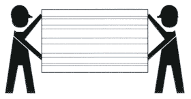
When carrying multi skin factory assembled or barrel vault rooflights, care must be taken not to twist them. They should be carried at all time by two men, as illustrated, or more in the case of long units.
Always wear protective leather gloves to avoid cuts from sharp edges of sheets.
Cutting and Drilling
Cut rooflights with a power saw having a 40/60 grit diamond blade operating at minimum speed. Alternatively, they can be cut with a hacksaw having 6 to 8 teeth per centimetre held at a shallow oblique angle.
Holes must never be punched through rooflights as this can cause cracking around the holes. This reduces the pull through performance of the fasteners (i.e. the force required to pull the rooflight over the fastener when subject to suction loadings).
Use standard metal drills for drilling GRP. Drill thermoplastics with masonry type drills, or metal drill bits having a point angle of 1300. To accommodate thermal movement in thermoplastic rooflights, the diameter of the holes where the primary fasteners are to be fixed, must be at least 10mm diameter.
COSHH Regulations
For GRP, polycarbonate and PVC when cutting or machining with power tools, a non-toxic biological inert dust is produced. These dust levels should be kept as low as reasonably practical, and must not exceed the Occupational Exposure Limit of 10mg/m3 ? 8 hour TWA value.
When working outdoors, it is most unlikely that these levels could be reached. When working indoors or in confined areas, adequate ventilation should be provided. When extensive operations are necessary, suitable dust extraction equipment should be used.
When cutting sheets, operators should always wear suitable dust masks and goggles to avoid any irritation in the nose, throat, lungs and eyes. In isolated cases, dust may cause slight transient irritation. Should these effects be prolonged or any sign of rash occur, medical advice must be obtained.
All exposed skin must be thoroughly and frequently washed with soap and water. Any eye contamination must be washed with copious amounts of clean water.
Sheet edges can be sharp, always wear gloves when handling sheets.
Do not smoke in or near stores or working areas.
Whilst the use of long length rooflights may reduce the number of end laps and reduce material costs, site conditions must be considered. A long length rooflight (exceeding 7 metres) is relatively light in weight, and when handled on high exposed buildings, can be awkward to handle even in mild blustery conditions.
In the event of a fire involving rooflight material, the safe extinguishers to use are:
- Carbon Dioxide
- Water
- Foam
- Dry Powder
Noxious fumes may be produced which can contain carbon monoxide, carbon dioxide and soot particles. Breathing equipment is advisable in enclosed areas.
Top of page
|
? |
|